

Arterial Flow Model
The arterial model that the team received from Guidant at the beginning of the project included a soft urethane aorta with renal, iliac and coratid arteries and a set of PVA coronary arteries. Designers at Guidant had been using the arterial model by perfusing it with steady flow at well below physiologic pressure. When we increased the pressure inside the arterial model, many unforeseen problems from component connections and the manufacturing process arose. Some of these new problems fell outside the scope of the project description but they all had to be addressed in order to proceed with the development of the pulsatile flow regulation system. Once the model was adapted, we took accurate measurements and determine the final valve settings for producing life-like conditions throughout the model. The main issues to be resolved were:
Coronary arteries
Guidant designed the base of coronary artery to have an inner diameter slightly larger than the outer diameter of the coronary take-offs on the aortic arch so that the arteries would simply slip over the take-offs. At low pressure, this attachment method worked but at physiologic pressure the coronary arteries slid right off the aorta. The team's first solution was to use the same plastic clamps used to connect sections of rubber tubing to hold the two together, but the coronaries still slid off the aorta under high pressure flow. So the team consulted with the project sponsors at Guidant and decided to sacrifice the modularity of the coronary arteries (the plug-n-play ability) and permanently glue a right and left coronary artery to the aortic tree. This solution looked promising for several days after gluing until the glue caused the model to dry out and crack during use. The PVA coronary arteries tore and, more significantly, the coronary take-offs on the aortic model were also damaged. The team was able to acquire from Guidant an additional aortic tree but it lacked any of the branching arteries included on the aortic model we were currently using. Rather then remove and replace all of the branching arteries, the team decided to remove the end of the aortic arch containing the coronary take-offs from the new model by cutting along a seam and glue it to their existing model.
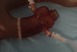
Figure 15: Aortic model with new coronary take-off section
The polyurethane used to make the aorta glues to itself quite well using urethane specific glue. The seal between the new segment of the aorta and the rest of the existing model has proved very solid. We have never experienced leaks at the seam and experimental measurements of the magnitude and shape of the pressure waveform in the aortic arch before and after the transplant indicate that we have not significantly changed the material properties of the aorta.
After repairing the aorta, the team decided to attach the coronary arteries using plastic connectors shown below.
Figure 16: Connection between aorta and coronary artery
The connectors fit into the coronary artery and the coronary take-off and screw together to form a seal. The use of the connectors introduces a short section of rigid vessel with the slightly smaller inner diameter. The team has chosen to accept this deviation from tissue-simulating materials and small loss of compliance because of the difficulty in attaching the coronaries by any other means. The interface between the aorta and the coronary arteries is a problem acknowledged by Guidant. There is currently a design team at Guidant working to develop a better connector. Any progress they make could easily be incorporated into the work done by the Basement BioWorks team. This attachment method was never part of the project goals defined by the team and we chose to proceed with this non-ideal connection.
Valve Placement
Another important step towards finalizing the model was moving the valves used to create resistance through a vessel outside of the field of view of the fluoroscope. The fluoroscopic field of view is basically the area of interest during a surgical procedure. The field of view for the renal and coronary arteries is outlined in the pictures below. One can see a flow restriction valve around the renal artery, inside the field of view. This would appear as an opaque area under fluoroscopy and obstruct the view of any surgical devices being used inside the model.
Figure 17: Fluoroscopic field of view (A) PVA coronary arteries. (B) Renal arteries prior to change in valve placement.
The valves were moved out of the field of view by creating converging flow networks from the arterial branches using a series of "Y" connectors. The flow restriction valves were then placed at the end of the network.
.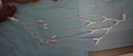
Figure 18: Converging flow network with valve
The converging network also allowed for much more accurate velocity measurements using an in-line flow meter following the valve and the ratio of the cross-sectional areas to determine the velocity in the artery. Before the networks were in-place, velocity measurements were made by capturing the flow out of all of the arterial branch vessels over a period of time. Using the flow meter, we can continuously visualize the velocity profile while adjustments are made to the valve settings allowing for much faster tuning than the iterative, guess and check method.
The full arterial model is shown below.
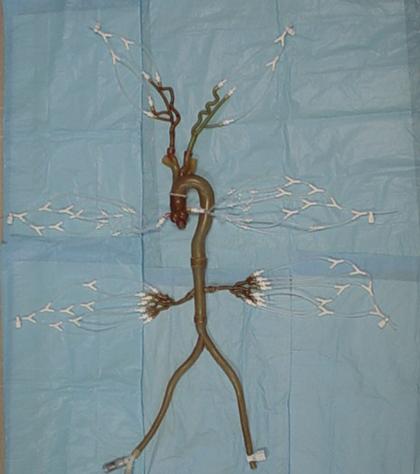
Figure 19: Arterial Model with networks and distal valves.
Harvard Pump Settings
The team also had to determine what standard set of operating conditions we would define as physiologic for the remainder of testing. This involved selecting settings for each of the three variables on the Harvard Apparatus, the pump used to produce pulsatile flow. These three variables include, stroke rate, stroke volume and stroke ratio (systolic/diastolic). The team has chosen to perfuse the model with pulsatile flow at
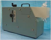
Figure 20: Harvard Apparatus
Beating Heart Prototype
Purpose
The other goal of this project is to create the physiologically realistic movement of the coronary arteries. Furthermore, the means by which this motion is created must not be visible under the fluoroscope. The team chose to produce this motion by using two fluid-filled, thin walled chambers. As the chambers fill with fluid, the walls expand and thus simulate the expansion of the heart chambers as they fill with blood. The expansion of the two chambers must also be offset from each other to simulate the biphasic motion of the heart.
There are many factors which affect the motion exhibited by the chambers. To better understand the system, our team designed and built a simple critical function prototype. Our main goals were to ensure that it would be possible to create the necessary biphasic motion by means of simple valve actuations and to determine what type of driving forces were needed to properly expand the chambers. Subsequent goals of the prototype were to define the effects of different system variables on chamber expansion. This information is useful when tuning the expansion of the chambers for improved realism.
Structure
The main components of the critical function prototype were two balloons of different wall thickness and internal space-fillers of different diameters. Each balloon represents two of the four chambers of the human heart. The smaller balloon represents the combined left and right atria of the heart while the larger yellow balloon represents the two ventricles of the heart. The atrial chamber actually consisted of two balloons fit around each other to create a thicker wall. Both chambers had an inlet and outlet tube attached using tube clamps or cable ties. This provided a quick-release method of fixing the tubes to the balloons. For this prototype, the quick-release allowed for a wide range of system configurations to experiment with chamber location and the variation of inlet and outlet diameters.
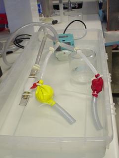
Figure 21: Experimental setup of the heart module critical function
prototype arranged with both chambers in parallel
This basic prototype allowed us to test various design concepts with the same basic hardware. Figure 16 shows the experimental setup of the prototype connected in parallel with a steady submersible pump. The functional prototype allowed the team to determine the affects of the following design parameters on the heart wall motion:
· Wall thickness
· Valve placement
· Tubing length and diameter
· Inlet/Outlet ratio
The wall thickness of the balloon chamber did not have a significant effect on the expansion and contraction rate. The size of the inlet and outlet diameter proved to be the dominant factor. The size of the inlet diameter determined the expansion rate as the balloon filled, while the outlet diameter determined the rate of contraction. The outlet diameter needed to be larger then the inlet diameter to simulate a realistic contraction. The optimal difference between the two was experimentally determined to be .25 inches. The team experimented with placing a valve between the atrium and ventricle chambers in a series configuration to create an offset in filling, but this did not prove to be necessary. Simply placing a length of tubing between the two chambers was sufficient to produce the desired phase delay. The length of the tubing determined the delay in ventricle filling. The team also experimented with placing the atrium and ventricle chambers in parallel and using exit valves to control filling. In this case, it was necessary to evenly divide flow from the pump between the two chambers or else one chamber would continuously fill. Out of all these configurations, the parallel heart configuration was the most successful at producing realistic, repeatable biphasic motion.
The final critical function prototype depicted above consisted of two single-balloon chambers connected in parallel to a submersible 500 gal/hour steady pump. This pump produces more flow than is required to drive the heart prototype so the excess fluid is diverted away from the model using a bleed valve. This was also useful for experimenting with the pressure inside the heart model. By partially covering the bleed valve it is possible to change the pressure inside the chambers. The outlet valves on both chambers are .25 inches larger in diameter than the inlet valves. For experimenting with the heart prototype, we controlled the chamber outlets by covering the tubing with our fingers rather than using valves or circuitry. This allowed us unlimited flexibility in the rate of filling and emptying.
System Configurations
Alongside the development of the functional heart prototype to produce biphasic motion, the team experimented with different system configurations to integrate the beating heart and the aortic flow model. We tried four different system configurations diagramed below. The "A" and "V" label the atrium and ventricle chambers of the heart respectively, and are inflated sequentially to create biphasic heart motion.
Figure 22: Pre-Aorta, Series configuration from Harvard Pump→heart→aorta
In the Pre-Aorta system configuration the heart model and the aortic model are placed in series, with the heart preceding the aorta. Check valves were placed before and after the heart to prevent back flow through the system and to attempt to isolate the aortic model from pressure changes in the heart.
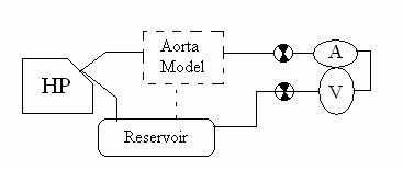
Figure 23: Post-Aorta, Series configuration from Harvard Pump→aorta→heart
This configuration is similar to the pervious series configuration except that the aortic model precedes the heart model.
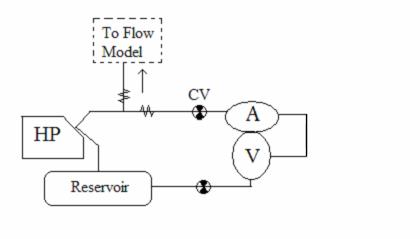
Figure 24: Parallel System, Flow from Harvard pump splits to heart and aorta
In the parallel system configuration, flow from the Harvard pump is divided evenly between the aortic model and the heart prototype. Check valves are used to prevent back flow through the system.
Figure 25: Two Pump System, The heart and aorta are decoupled
In the final system configuration, the heart and the aortic models are two independent systems. The aortic model is driven by pulsatile flow from the Harvard pump while the heart model is connected to a steady pump.
The team built these four system configurations using the preliminary aortic model and the functional heart prototype. Both series systems proved unfeasible because they could not produce sufficiently high pressures in the two elements. Using the Pre-Aorta configuration, a physiologic pressure of 120/80 mmHg could not be produced in the aorta. In the Post-Aorta system configuration, the pressure drop across the aorta proved to be large enough that the flow exiting the aortic model through an iliac artery did not have sufficient pressure to inflate the heart model. In the parallel configuration, the flow from the Harvard pump was divided between the heart prototype and the aorta and the volume was insufficient for reaching physiologic pressure in the aorta.
So the team chose to decouple the heart model and the aortic model and run the heart off of a submersible steady pump. The final design configuration is shown in the diagram below. The atrium and ventricle of the heart model are connected in parallel to the submersible pump. Two solenoid valves control the outlets of the heart chambers. The timing of the valve opening is controlled by an electric circuit which is triggered by a pulse from a switch placed inside the Harvard pump to indicate when the pump is at the forward limit of a stroke.
Figure 26: Final Two-Pump configuration