

Heart Prototyping Fundamental Concept After creating and testing the critical function prototype,
the design of the final heart prototype was initiated. The final prototype must contain components
similar to those used in the critical function prototype, but have the appearance
of an anatomically correct human heart.
Therefore, our design must have two, thin-walled chambers stacked vertically
(from a front view) with a separate inlet and outlet port for each chamber. This is shown in cross section in Figure
27. 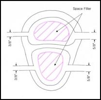
Figure 27: Cross section of the initial conceptual prototype for the Beating Heart
In our initial design concept, we planned on using space fillers inside the chambers to allow for greater expansion with less fluid flow, as shown above. However, this concept was generated with the idea that the system must minimize fluid flow since the Harvard pump would drive both the beating heart and aortic modules. By decoupling the two systems, the need to minimize flow through the heart was eliminated and consequently the space fillers were eliminated from the final design.
From the critical function prototype it was also discovered that the pressure to the heart model could be easily increased and decreased by adjusting the bleed valve output. Therefore, as opposed to designing around a given pressure, our team designed around the optimized inlet/outlet diameter difference of 0.25 inches. This allows for flexibility in both the thickness of the heart chamber walls and the materials used to fabricate the heart. For the first prototype a wall thickness of 1/8 inch was used for the ventricular chamber and 3/16 inch for the atrial chamber.
Solidmodeling
The human heart is a complex organ with various changes in curvature and surface properties. Consequently, this creates quite a challenge when attempting to replicate the heart in a three dimensional software package. There are, however, commercially available packages that have already created a geometric representation of the heart with great detail. Guidant has provided our team with a commercially available surface model produced by Viewpoint.
Figure 28: (A) A front view of the Viewpoint surface model of the human heart.
(B) A view of the simplified model of the human heart provided by Guidant.
Unfortunately, this surface model is far too detailed for the purposes of this project. Furthermore, the high level of detail of the model resulted in various geometric errors when importing the file from Initial Graphics Exchange Specification (IGES) format into the 3D software. Therefore, a more simplified model of the heart was used. Guidant has also provided our team with a simplified heart model, which they currently use to fabricate the solid hearts used with the SAM. Using this simplified model also allows the interface between the heart and the aorta to remain unchanged. Most of our modifications to the model were to the inside of the heart. Therefore, the exterior shape of the final prototype closely resembles the geometry of the current Guidant heart.
Modeling
The Solidworks 2001 three dimensional solid modeling software package was used to make our modifications to the heart model. The base model for the heart is shown above in Figure 28(B). This model was modified at the beginning of the SAM project by Guidant. The right atrium was removed and the posterior and anterior sections of the right ventricle were slightly indented.
For the purposes of our model, the right atrium would be re-introduced and the right ventricles would be modified to resemble their previous shape. The first step in the modeling process was to section the heart into three main modules consisting of:
(1) The two atrial chambers
(2) The mid-section which would interface with the aorta
(3) The two ventricular chambers
Figure 29: Exploded view of simple heart model after initial sectioning
This sectioning allowed for each piece to be worked on independent of the other sections. Section (1) consisted of various undercuts and sharp geometry, which made it almost impossible to work with. Therefore, the single atrial chamber was replaced by a two-chamber atrial assembly. Using the guide contours of the original atrium, a new atrium solid was created. This chamber has a larger cross section of approximately 2 inches and was shelled with a wall thickness of 0.125 inches. The original design was for a wall thickness of 3/16 inch but due to the geometry of the chamber, the thickness was limited to 1/8 inch.
Section (2) is critical because it is the interface with the aorta. Therefore it must be able to hold the aorta in the same position each and every time. Guidant has done an excellent job in creating this interface and the team decided, if at all possible, to limit the modifications to this section. Therefore, the inside surfaces were left alone while the outer surfaces were thickened to match the modifications to Section (3). This also allows us to leverage the existing coronary artery interface.
Section (3) consists of the chamber representing the two ventricles. The surface of this section was first straightened by importing the model section into the Rhinoceros 3D modeling software. The B-spline curves were slightly modified to remove the curvature from the anterior side. We also attempted to enlarge the right ventricle but our modifications were limited by geometric constraints. The section was re-imported into Solidworks and the surfaces were thickened and joined as a single section. This created a hollow section with wall thickness of 0.118 inches. Again, the wall thickness of this chamber was limited by its geometry.
Figure 30: Removal of "indentions" in Section (3) by modifying the B-spline curvature
After being processed individually, cores were created for both chambers for use during the manufacturing process. The sections were then joined in an assembly file. Due to the modifications on the surface of the ventricles, Sections (2) and (3) had to be lofted together to compensate for the mismatch in curvatures. Figure 31 shows the final model joined together as one part.
Fabrication of Prototype
Since our beating heart prototype closely resembles the existing SAM heart, we are able to leverage a large portion of the current manufacturing process. The current SAM hearts are created from either silicon or urethane based material. Regardless of the material chosen, a common set of molds and cores can be used to produce different models.
Guidant has developed a five-step process to fabricate their SAM heart models. This process cleverly utilizes the outer surface of the model as a means to secure the coronary arteries to the heart wall. As seen in Figure 32, the final SAM heart model contains multiple grooves, which the coronary arteries fit inside of. This layer is known as the myocardium. These grooves can be modified from model to model depending on the specific focus of each experiment conducted with the SAM. Our team leveraged most of this manufacturing process, only slightly varying a couple of steps to incorporate our design changes.
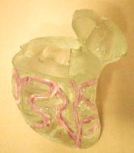
Figure 32: A side view of the original SAM heart model with coronary grooves highlighted.
In order to create this synthetic heart, multiple model positives must be first created. Using the final model described in the previous section, four other parts are created. By enlarging and reducing the size of Section 3 of the model, we were able to create the enlarged heart and the reduced heart. The reduction was done by scaling Section (3) down by a factor of 0.87. This allows for a 0.32 inch myocardial layer to hold the coronary arteries.
Similarly, using Section 1 and 3, an inner core was created for the atrium and ventricular cavities. This cores are responsible for creating the inner cavities of the model. To ensure proper alignment of each core, a series of core registration pins was added to each of the models. The pins serve a dual purpose. They act to align and hold the cores in place and create the holes for the inlet and outlets of the chambers. The largest pin on the ventricles is used to pass a tube that will later connect the root of the aorta to the Harvard pump. All five models are illustrated in Figure 33. Figure 34 shows a cross section of the heart with the inner tube attached.
Figure 33: Five models produced in
Solidworks for use during the manufacturing process.
(A) Reduced Model (B) Full Model (C)
Enlarged Model (D) Atrium and Ventricle cores.
Figure 34: Cross section of a side view of the final heart solid model.
Originally these models were to be produced on a Guidant SLA
machine in Temecula. However, due to
file compatibility issues, we were not able to create the models by conventional
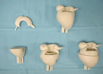
Figure 35: 3D powder printed parts prior to molding
The first step in this manufacturing process is to create a master mold which will serve as the casting platform for the heart. This master mold is created from the enlarged heart model. This mold is poured in four separate sections allowing each section to fully cure before the next is added. The first layer is a base layer which holds the heart in place. The second layer creates the lower half of the mold, which encompasses the enlarged ventricle section. The third layer covers the midsection of the heart up to the middle of the atria and creates the core geometry to interface with the aorta. The final layer covers the atria and creates the injection and vent holes for the mold. Ventilation, injection and clamping pins were added as needed.
Figure 36: Master Mold with only the Skin Layer poured
Once this mold is created, the model is carefully removed from the mold. Next, a series of skins is produced which lie inside the Skin Layer of the master mold and are responsible for creating the geometry of the reduced and full sized heart. These skins will also be responsible for creating the grooves in the myocardium later. One at a time the other two models are placed into the lower half of the mold and the skins are poured from a TAP urethane material. This is illustrated in Figure 37. This manufacturing method allows from multiple model configurations to be created from a single master mold.
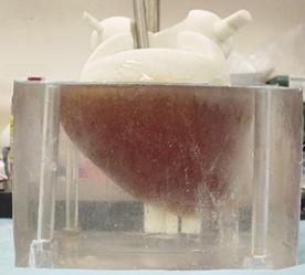
Figure 37: Casting of the TAP urethane skin
While these molds are being created, two separate molds are also created in parallel. These molds will create the water soluble wax cores. These molds are created in a similar fashion to the master mold but, they are only sectioned once. They are allowed to cure overnight and the models are removed in the morning. The cores are then cast from a water soluble jewelers wax.
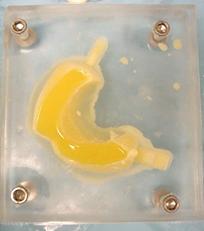
Figure 38: Wax casting of atrium core
Next, the master mold is reassembled with the two cores in place and the skin for the reduced heart. The reduced heart is then cast from a silicon material. We have chosen a silicon polymer known as Dragon Skin © which is produced by Smooth-On. This polymer has a Shore Hardness of 10 on a Shore A scale and is very durable with a large elongation to tear ratio of 1000%.
Once cured, the silicone reduced heart mold is removed from the mold and urethane coronary arteries are pinned to the ventricles. These urethane arteries will create the grooves in the myocardium in which the SAM arteries will be embedded. This allows the model to have modular, plug-n-play functionality. This is demonstrated in Figure 39
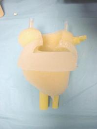
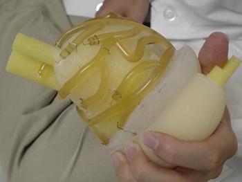
Figure 39: (A) Reduced silicon heart model (B) urethane arteries pinned to the reduced heart
This model is placed back into the master mold with the full skin in place and the final model is cast from the same silicon material. The model is allowed to cure for five hours and then removed from the mold.
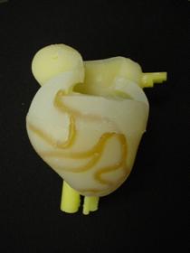
Figure 40: Full heart with cores and urethane arteries still embedded
The final steps are to remove the arteries and wax cores. A thin line was cut above the arteries to allow them to be removed. This creates the grooves to hold the coronary arteries in place during use. To remove the cores, the model is placed under running water until all the melted wax has been removed.
Once the final heart has been created, the inlet and outlet tubes were attached by applying a layer of silicon to the tube/heart interface. Silicon tubing was selected for this because of the amazing bonding strength of similar silicon based materials. Furthermore, the diameter of the holes in the heart is equal to the inner diameter of the tubing. This causes the material surrounding the tube to be compressed against the tube when it is inserted, thus helping seal the interface. The model was tested under normal operating conditions and no leaks were found. Furthermore, the heart was able to maintain the plug-n-play functionality because no adhesives were used to hold the aorta onto the heart. Figure 41 shows the finished heart attached to the aorta.
Figure 41:Finished silicon heart interfaced with the SAM aorta.
Red arrows
mark heart system flow, blue arrows mark aortic system flow.
Synchronization Circuit: Heart Actuation
To achieve realistic heart wall motion the expansion and contraction of the heart chambers must be synchronized with the motion of the Harvard pump. It should appear as though the beating of the heart is pushing fluid into the aorta despite the fact that the two systems are independent. As the piston inside the Harvard pump moves forward, the atrium expands and ventricle contracts. Then when the piston moves backward, the atrium contracts and the ventricle expands. To produce this biphasic heart wall motion, we place two solenoid valves at the outlets of atrium and the ventricle. We can control the expansion and contraction of the two chambers by opening and closing these valves. When an outlet valve is closed, the preceding chamber will expand. When the valve is opened, the chamber contracts quickly because the outlet diameter is much larger than the inlet. An electrical circuit is used to synchronize the aortic model driven by the Harvard Pump and the beating heart model driven by a steady pump.
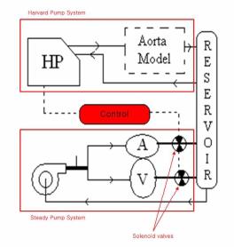
Figure 42: The synchronized aortic model and beating heart model
Electronic Control Circuit
The diagram below details the circuit used to control the outlet valves. This circuit consists of three major parts: The first part generates a clear signal, the second part creates a second signal and the third controls the opening and closing of the valves.
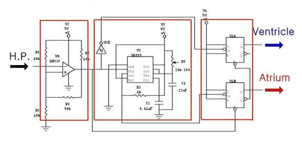
Figure 43: The electrical control circuit
The pulse from the Harvard pump is not clear enough to make logic high and low for electronic circuit. The pulse ranges from 1V to 3.5V. Because general electronic components consider a signal over 0.3V as logic high, this range is always considered high. To address this problem, we send the Harvard pump signal through an Op-Amp which is set to recognize only signals over 1.5V as a logic high signal. As a result, we get the 0V to 5V clear input signal for the control circuit.
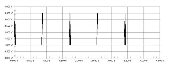
Figure 44: The signal from Harvard pump
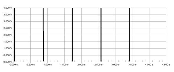
Figure 45: Clear signal after OP-Amp
A switch has been placed inside the Harvard pump to produce an electrical pulse when the piston is at the forward limit of a stroke. The control circuit receives this pulse signal directly from the Harvard pump and uses it as a source signal. Specifically, the falling edge of the pulse from the pump is used as the input signal.
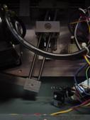
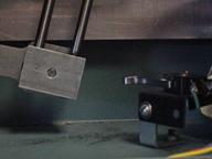
Figure 46: Switch inside Harvard pump
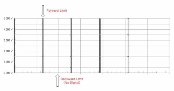
Figure 47: Unmodified signal from Harvard pump
Unfortunately, the Harvard pump only indicates when it is at the forward limit of a piston stroke. The heart actuation requires a trigger at the forward limit and the backward limit of a stroke. (Figure 47) Therefore, we need to create another signal at the backward limit of the pump stroke. This is the function of the first half of the control circuit labeled Signal Creating. By using a monostable timer circuit, we copy the input signal from the pump switch and extend the pulse duration time. As a result we can create another falling edge. We can also change the timing of second edge by adjusting the potentiometer (Ra) which allows us to control how long the atrium and ventricle expand during one heart cycle. We can calculate the time interval between the first signal and second signal using the formula below.
Time interval, T = 1.1 * Ra * C
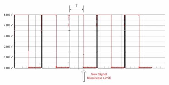
Figure 48: Harvard pump signal modified to produce two inputs
Biphasic Expansion and Contraction
The control circuit is made using two JK flip flops. These flip flops are triggered by the falling edge of a pulse and then maintain their current state until another falling edge appears. This produces the biphasic signal shown in the following diagram. A logic high signal means that the control valve is open and the chamber is emptying.
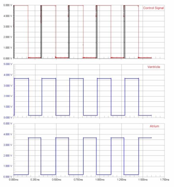
Figure 49: Signal inputs and valve positions
Control Box
To protect electronic circuit from water and allow for easy connection to the heart model, we build a control box. We placed the two solenoid valves and circuit board inside an acrylic box, forming one package. It has ON-Off switch and BNC connector sample the signal from the Harvard pump in front side.
Figure 50: Control box