

Arterial Flow Model
To develop the flow control valve system and verify that it produced physiologic flow conditions inside the arterial model, the team used a pressure catheter to sample the pressure inside the aorta and branch arteries. The catheter was introduced into the iliac artery and connected to a data acquisition system to display the pressure waveform and determine the mean pressure.
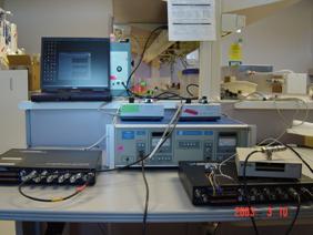
Figure 51: Data Aquistion System
By restricting the flow through the arterial model the team was able to reach a the peak physiologic target value of 120/80 mmHg inside the aortic arch. By placing a jar half filled with air in parallel with the flow model, we were able to add compliance to the flow model to compensate for the rigid tubing used to make pump connections. This added compliance helped to damp out the pressure reflections caused by joints and rigid tubing and produce a smoother waveform. The pressure waveform measured in the aortic model is shown below. The compliant urethane aorta produced a life-like reduction in pressure magnitude with distance from the heart.
Figure 52: Aortic Pressure Waveform
To measure the flow velocity through the branch arteries, we placed in-line flow meters behind the flow restriction valves follow the converging networks.
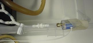
Figure 53: In-line flow meter
By tuning the distal valves, the team was able to maintain physiologic pressure inside the aorta while producing accurate flow velocities in a target region of the model. The target and measured flow velocities as well as the required valve settings are shown in the table below.
Table 2: Flow rate and valve settings
Our project sponsors were interested to know how the use of coronary arteries with partial occlusions to simulate disease affected the pressure and flow rate. We found that the magnitude and shape of the pressure waveform inside the model did not change significantly with the diseased coronaries. The velocity increased slightly due to the smaller lumen size. These results are important to our sponsors at Guidant who intend to use the model at in their labs but do not have the extensive data acquisition systems available at Stanford to tune the model every time a new coronary artery design is used. Using the recommended valve settings above, the pressure and flow rates inside the model should remain physiologically realistic despite the use of diseased coronary arteries.
Heart Wall Motion
The team is quite pleased with the biphasic contraction and expansion motion exhibited by the heart prototype. Unfortunately, the model has not been observed by a cardiologist to assess the realism of the heart due to time constraints.
Originally the team had planned on validating the motion of the heart wall by both visual inspection by a cardiologist and empirical data taken from two 3D angiogram images as explained in earlier sections. However, both of these validations were heavily reliant on the timely completion of the silicon heart prototype. Due to two separate events beyond our control, mainly software incompatibility and the derailment of the train carrying our casting supplies, the prototype was not finished on time. Thus, we were unable to physically validate our model as planned.
We did, however, create a method of predicting the motion of the coronary arteries. The main goal of the beating heart is to properly displace the coronary arteries to add a sense of clinical realism to the SAM. Thus the most important aspect of the heart wall motion is the displacement of the ventricle walls. We have created a finite element model for the purposes of predicting the motion of the ventricle walls and to aid in the improvement of subsequent prototypes.
The finite element model uses the geometry of the lower half of the heart, imported from the CAD model, as well as the material properties of silicon to predict the displacement of the walls under a given pressure. A CAD surface model of the lower half of the heart was imported into ANSYS 5.7 and meshed with the auto-mesh tool.
Figure 54: Transformation of Solidworks CAD file to ANSYS meshed finite element model.
Since the lower half is fixed rigidly to the upper half of the heart, a zero displacement boundary condition was added to the upper most edge of the heart. To simulate the 1.16 psi pressure created by the water inside the chamber, a uniformly applied pressure was added. The Dragon Skin silicon used in our model has a tensile modulus of 475psi and a poisons ration of 0.48. Figure 55 shows the applied boundary conditions.
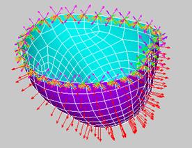
Figure 55: Boundary conditions applied to ANSYS model. Orange triangles represent constraint of all D.O.F. Red arrows represents the uniform internal pressure applied to the normal to the inner surface.
To validate the accuracy of the model, it was first analyzed against an older heart which Guidant had previously created. This heart was made of urethane with an assumed tensile modulus of 425 psi. A series of displacements were measured from the urethane model and compared the output from the FE model. Table 3 shows the results of both analysis.
Table 3: FEA and validation model results (inches)
Six zones were chosen to represent the motion of the heart wall. The model correlates strongly with zones 2,3,4,and 6. Zones 1 and 5 both had unusually thin or thick walls and should therefore be eliminated form the analysis. Although this validation is not ideal, it gives the FE model a creditability in prediction the motion of the heart.
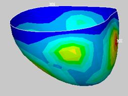
Next an analysis was done for the model made of silicon. Figure 56 shows the contour plot of the resulting displacements.
It is evident that the displacement of this model does not completely correlate with the data taken from the coronary arteries. The magnitudes of the displacements agree with the data, however, the displacement geometry is less than ideal.
With this information, the model was improved by varying the wall thickness at key points and the model was run again. Considering the location of the coronary arteries shown in Figure 57, discrete areas of the model were targeted during the analysis.
Figure 57: Target areas for coronary displacement analysis. Numbers show the approximate location of the target areas.
The resulting displacements were recorded and analyzed against the coronary artery data. This process was iterated until the design was optimized. Unfortunately, not all targeted displacements can be met. The Table 4 shows that five of the seven zones will achieve the desired displacements when the model is run at 3 psi.
![]()
Figure 58: Displacement contour plot of optimized model (inches). Uniform pressure applied, 3psi
Table 4: Comparison of optimized FEA model with actual displacement values (inches)
Considering the above results it is our recommendation that, for future prototypes, a non uniform wall thickness is applied to the ventricle walls in accordance with Figure 59 below.
Figure 59: Optimized model with areas of constant thickness color coded. (A) Front view. (B) Rear view (C) Top view